Introduction
Specify the wrong connector pin size and the consequences compound fast. A mismatched pin can compromise crimp retention, exceed current capacity, or introduce arcing and signal loss — and in safety-critical applications, it can void regulatory compliance entirely.
Common failure modes from incorrect pin sizing include:
- Poor crimp quality and reduced pull-out force
- Insufficient current capacity leading to overheating
- Incompatibility with connector housings or mating components
- Signal degradation or intermittent faults
- Non-compliance with automotive, medical, or industrial standards
Reading pin size charts correctly is fundamental to component selection and long-term system reliability. This guide covers what connector pin size actually means, how to interpret pin size charts, how dimensions are specified and validated, and where selection errors most often occur.
TLDR
- Connector pin size covers contact diameter, barrel dimensions, and wire gauge range—it's a multi-dimensional spec, not a single number
- Standard contact size designations (e.g., size 8, 12, 16, 20) are AWG-based categories mapping to specific wire gauge ranges and current ratings
- Pin size charts link contact size to wire gauge, crimp barrel dimensions, amperage capacity, and shell/insert arrangement for proper system matching
- Using the wrong pin size causes crimp failures, arcing, or signal loss—and can void regulatory compliance
- For high-reliability applications, dimensional consistency across the full production run matters as much as nominal size
What Connector Pin Size Actually Means
Connector pin size is a multi-dimensional set of specifications. It encompasses the contact's outer diameter (OD), crimp barrel inner diameter and length, tip geometry, overall pin length, and the rated wire gauge range it accommodates—not a single measurement.
Understanding Contact Size Designation vs. Actual Dimensions
A "size 16" contact is an industry designation, not a literal 16mm or 16-unit measurement. It maps to a specific wire gauge range (typically 16–20 AWG) and current rating. According to MIL-DTL-5015 documentation, contact size designation is "an assigned number denoting the outside diameter of the engaging end of the pin contact. The larger the number, the smaller the size."
Key AWG-to-contact-size mappings include:
- Size 20: 20–24 AWG
- Size 16: 16–20 AWG (conductor diameter range: 0.032–0.050 inches)
- Size 12: 12–14 AWG
- Size 8: 8–10 AWG
These values vary slightly between connector series and standards bodies, so always cross-reference the specific manufacturer's chart.
Pin Size, Shell Size, and Insert Arrangement: Three Separate Parameters
Shell size governs the connector body's outer dimensions (e.g., sizes 9, 11, 13 up to 25). Insert arrangement determines how many contacts of which size fit inside that shell. Pin size governs the individual contact's dimensional and electrical specifications. Each parameter is defined independently, but choosing one constrains the options for the others.
For example, selecting Shell Size 25 with Insert Arrangement 'J35' in a MIL-DTL-38999 connector results in a connector with 128 cavities, all accepting Size #22D contacts.
Pin Size as Both Mechanical and Electrical Parameter
The contact cross-section directly determines current-carrying capacity: larger diameter = lower resistance = higher rated current. The crimp barrel dimensions determine mechanical retention strength with the wire. Both functions—electrical and mechanical—are governed by the same size specification, which is why pin size is a design constraint, not just a label.
How Material, Plating, and Environment Affect Pin Performance
Real-world pin performance differs from the values listed on datasheets due to:
- Material choice: Copper alloy grade affects conductivity and formability
- Plating type: Nickel for power/control circuits; gold for low-voltage sensor and signal circuits
- Manufacturing method: Die-rolled, stamped-and-formed, or machined contacts each produce different dimensional tolerances and consistency levels
Operating environment and duty cycle add further variables. Elevated temperature reduces current capacity. Vibration and repeated mating cycles cause gradual wear that shifts dimensional fit over the connector's service life.
Key Dimensions in Connector Pin Size Charts
Standard connector pin size charts contain these column headings:
- Contact size designation
- Compatible AWG wire gauge range
- Wire insulation OD range
- Current rating (continuous)
- Crimp barrel dimensions (ID and length)
- Plating specification
- Applicable connector series
AWG-to-Contact-Size Mapping in Detail
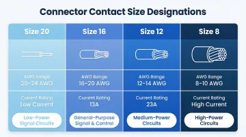
Standard AWG ranges for common contact size designations:
| Contact Size | AWG Range | Typical Application |
|---|---|---|
| 20 | 20–24 AWG | Low-power signal circuits |
| 16 | 16–20 AWG | General-purpose signal and control |
| 12 | 12–14 AWG | Medium-power circuits |
| 8 | 8–10 AWG | High-power circuits |
Always cross-reference the specific manufacturer's chart, as these values vary between connector series and standards bodies.
Current Ratings Per Contact Size
According to MIL-DTL-38999 and MIL-C-39029 documentation, typical continuous current ratings are:
- Size 16: 13 Amps
- Size 12: 23 Amps
Current rating depends on both contact size and plating. Silver-plated and gold-plated contacts of the same designation carry the same published rating. Physical size and base material determine the rating, not the final plating finish.
Additional Dimensional Parameters in Detailed Charts
Detailed charts include:
- Pin tip diameter: Determines insertion force and how quickly the mating interface wears under repeated cycles
- Overall contact length: Must match the connector body's cavity depth — even a fraction of a millimeter off can prevent full seating
- Crimp barrel dimensions: Set the acceptable wire gauge range and dictate which crimp tooling die you need
These dimensions can vary between manufacturers even when the contact size designation is identical. A pin that measures out-of-spec on barrel ID or overall length can cause crimp failures or connector body incompatibility — both of which are expensive to diagnose in production. Electropin's automatic die rolling process holds these tolerances consistently across the entire production run, with a documented defect rate of 1 in 600,000,000.
Plating Thickness in Charts
Gold plating is typically specified in microinches (µin) and affects both corrosion resistance and contact resistance. Standard specifications include:
- Gold top plate: 50 microinches (per ASTM B488 Type 3, Code C, Class 1.27)
- Nickel underlayer: 50-100 microinches (per QQ-N-290 Class 2)
Nickel underlayer thickness affects long-term wear performance, particularly in power and control circuits subject to repeated mating cycles.
How to Read and Apply a Connector Pin Size Chart
Reading a connector pin size chart correctly depends on knowing what you're looking for before you open it. Start by defining these four inputs:
What You Need Before Opening a Chart
- Wire gauge
- Circuit amperage
- Connector family/series
- Operating environment (temperature, vibration, whether signal or power circuit)
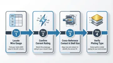
Step-by-Step Chart Navigation Process
- Locate wire gauge in the AWG range column to identify compatible contact size designations
- Confirm current rating for that designation meets circuit amperage requirement
- Cross-reference contact size with connector shell size and insert arrangement to confirm mechanical fit
- Verify plating type matches application (gold for signal/data/sensors, nickel for power and lighting circuits)
How Pin Size Chart Structures Differ Across Major Connector Families
MIL-spec charts (e.g., MIL-DTL-5015)
- Organize by shell size and insert arrangement with contact sizes specified per position
- A single connector series can host many different contact sizes (many-to-one approach)
- The engineer determines contact size from the insert arrangement, then cross-references its rating in a separate table
Industrial circular connector charts (e.g., M8/M12 per IEC 61076)
- Organize by coding and pin count with voltage/current ratings
- Ratings apply to the entire connector assembly — not individual contacts
- A 4-pin M12 A-coded connector carries a 4A rating because performance is a function of the integrated design
General-purpose connector charts (e.g., Deutsch DT/DTM series)
- Organize by series, amperage rating, and wire gauge range
- Each series is built around a single standard contact size (one-to-one approach)
- Selecting the "DT" series is synonymous with selecting a 13-amp, size-16 contact system
Pin vs. Socket Contacts in Chart Navigation
Pin and socket contacts share the same size designation, crimp barrel dimensions, and wire gauge range — but they're not interchangeable in chart navigation:
- Tip geometry differs: charts typically list pins and sockets separately despite identical size designations
- Contact construction matters: solid contacts and stamped-and-formed contacts of the same designation may require different tooling
- Check both: confirm your contact type (pin or socket, solid or stamped) before pulling installation specs
How Connector Pin Sizes Are Specified and Validated
How Pin Size Appears in Engineering Documentation
Engineering drawings, datasheets, and applicable standards include:
- Nominal contact size designation
- Dimensional tolerances (OD, barrel ID, length)
- Plating specification
- AWG range
Distinguish between "rated" values (design limits published by the manufacturer) and "tested" values (performance under qualification test conditions, which may differ from nominal).
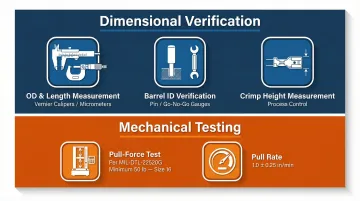
Common Measurement and Verification Methods
Dimensional verification:
- Vernier calipers or micrometers measure OD and confirm length
- Pin gauges or go/no-go gauges verify crimp barrel ID compliance
- Crimp height measurement — the primary non-destructive method for process control, per IPC/WHMA-A-620E
Mechanical testing:
- Pull-force testing (MIL-DTL-22520G) applies axial force to pull the wire out of the crimped contact
- Size 16 contacts require a minimum pull force of 50 pounds (222.4 Newtons)
- Pull rate is set at 1.0 ± 0.25 inch per minute for consistent, repeatable results
Lab measurement typically yields tighter results than field measurement. Field inspectors should account for measurement tool calibration.
Governed by Recognized Standards
The measurement methods above are only valid when applied against a defined specification. Connector pin dimensions are governed by:
- MIL-DTL series (e.g., MIL-DTL-38999, MIL-DTL-5015)
- IEC 61076 (M8/M12 industrial circular connectors)
- SAE standards
- USCAR for automotive
Deviations outside specified tolerances — even fractions of a millimeter — can cause failure at qualification testing, void warranty, or trigger regulatory compliance issues in medical and automotive applications.
Implications of Using the Wrong Pin Size
Direct Failure Modes Caused by Mismatched Pin Size
Oversized pin in undersized crimp barrel:
- Insufficient mechanical retention (low pull-out force)
- Potential wire strand damage
- Increased contact resistance that generates heat
Undersized pin crimped onto larger wire:
- Loose crimp with high risk of wire pull-out
- Arcing
- Intermittent connection failure
An improper crimp creates voids and air gaps between wire strands and the contact barrel, reducing effective contact area. This drives up electrical resistance, causing voltage drop and I²R heating at the joint.
That localized heat buildup can melt connector housings and wire insulation, degrade adjacent components, and in power-carrying circuits, create a fire hazard.
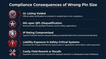
Downstream Compliance and Safety Implications
The physical failures above don't stop at damaged hardware. In regulated industries, they cascade into formal compliance consequences. Using out-of-specification pin sizes can:
- Invalidate UL listings: UL policy states that when a UL-Listed product is modified after it leaves the factory, the UL mark is voided
- Void MIL-spec qualifications: Military specifications operate on a strict Qualified Products List (QPL) system; using non-QPL contacts results in non-compliant assemblies
- Compromise IP ratings: Mismatched contacts that don't properly seat can create leak paths, rendering environmental seals invalid
- Create liability exposure in safety-critical systems (automotive, medical, aerospace)
- Force costly field rework or recalls
For industries subject to PPAP, AS9102, or similar process documentation standards, lot traceability back to a certified pin supplier isn't optional — it's a required part of the compliance record.
Common Misunderstandings About Connector Pin Sizing
Shell Size Is Not Pin Size
One of the most frequent sourcing errors is treating the shell or body size of a connector as a proxy for the contact pin size. A single shell size can accommodate multiple contact size designations depending on the insert arrangement. Always specify both parameters separately.
That distinction matters equally when reading AWG charts — because those values carry their own constraints.
AWG Ranges on Charts Are Designed Crimp Ranges, Not Hard Limits
The minimum and maximum AWG values in a pin chart represent the center of the acceptable crimp performance window. Using boundary values (the exact minimum AWG or maximum AWG) without crimp pull-force verification is risky and not recommended practice.
This same principle — that published values describe ideal conditions, not field reality — applies directly to current ratings and tolerances.
Datasheet Values Do Not Automatically Apply to Field Conditions
Published current ratings and dimensional tolerances assume controlled conditions: specific temperature, clean contacts, and correct crimp. MIL-DTL-38999 Section 6.1.2 explicitly states that test ratings are not equivalent to continuous operation allowances and that designers must establish their own safety factors.
Vibration, thermal cycling, chemical exposure, and duty cycle all degrade effective performance. Derating is strongly recommended for:
- Continuous electrical loads
- Multiple simultaneously energized contacts within a single connector (bundle heating)
- High ambient temperatures
- High altitude (reduces cooling and dielectric strength)
As a starting point, many aerospace and industrial designers apply a 50–70% current derating factor to connector contacts operating in high-temperature or high-vibration environments — then verify with pull-force testing before finalizing the design.
Conclusion
Connector pin size is a governing design parameter—not a passive label—that controls current capacity, mechanical retention, connector compatibility, and regulatory compliance throughout the life of the assembly.
Reading pin size charts correctly requires understanding multiple interdependent parameters: wire gauge, amperage, shell size, contact size designation, and plating type. Confusing any one of these with another leads to specification errors.
Published specifications only go so far. Matching nominal chart values to actual operating conditions, selecting a source that holds tolerances across a full production run, and verifying crimp performance under test are all requirements for reliable system design—not optional checkboxes.
Electropin's automatic die rolling process is built around that standard. With a documented defect rate of just 1 in 600,000,000, it produces custom connector pins with consistent dimensional accuracy across automotive, medical, and industrial applications where out-of-spec parts aren't recoverable.
Frequently Asked Questions
How to measure connector pin?
Use a vernier caliper or micrometer for outer diameter and overall length, and a pin gauge or go/no-go gauge for crimp barrel inner diameter. Take measurements on the contact body — not the tip or wire end — then compare against the manufacturer's dimensional drawing.
How to determine connector shell size?
Shell size is determined by the outer thread or body diameter of the connector housing (e.g., M8, M12, or MIL-spec sizes 8–24), and is selected based on contact count, contact size designations needed, and available panel or cable space. Note that shell size and pin size must always be specified separately.
What are the types of pin connectors?
The three main contact types are:
- Solid machined — best for soldering or precision crimp applications
- Stamped-and-formed — most economical, widest availability
- Die-rolled — high dimensional consistency, no material waste
Within each type, contacts are further categorized by plating (nickel or gold) and gender (pin/male or socket/female).
What does connector pin size mean?
Connector pin size is an industry designation (e.g., size 8, 12, 16, 20) that maps to a specific AWG wire gauge range, crimp barrel dimensions, and current rating. It is not a direct physical measurement in millimeters or inches. Always reference the manufacturer datasheet or relevant standard for corresponding dimensional specifications.
How does wire gauge relate to connector pin size?
Each contact size designation is designed to accept a specific range of wire gauges (AWG), with larger contact sizes accommodating heavier-gauge wire and higher current. The wire gauge determines which contact size designation is compatible. Using a wire outside the designated AWG range will result in a non-compliant crimp that may fail mechanically or electrically.