Introduction
Pick the wrong pin connector type and you're looking at intermittent failures, costly redesigns, or a production line that stops mid-run. It happens more than engineers expect — because the differences between connector pin types aren't always obvious until something goes wrong.
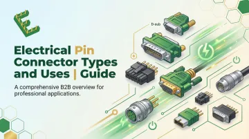
This guide breaks down the main types of electrical pin connectors, how each one works, where they perform best, and what to weigh when choosing between them.
TL;DR
- Electrical pin connectors use a metal pin contact to create a conductive path between two points in a circuit
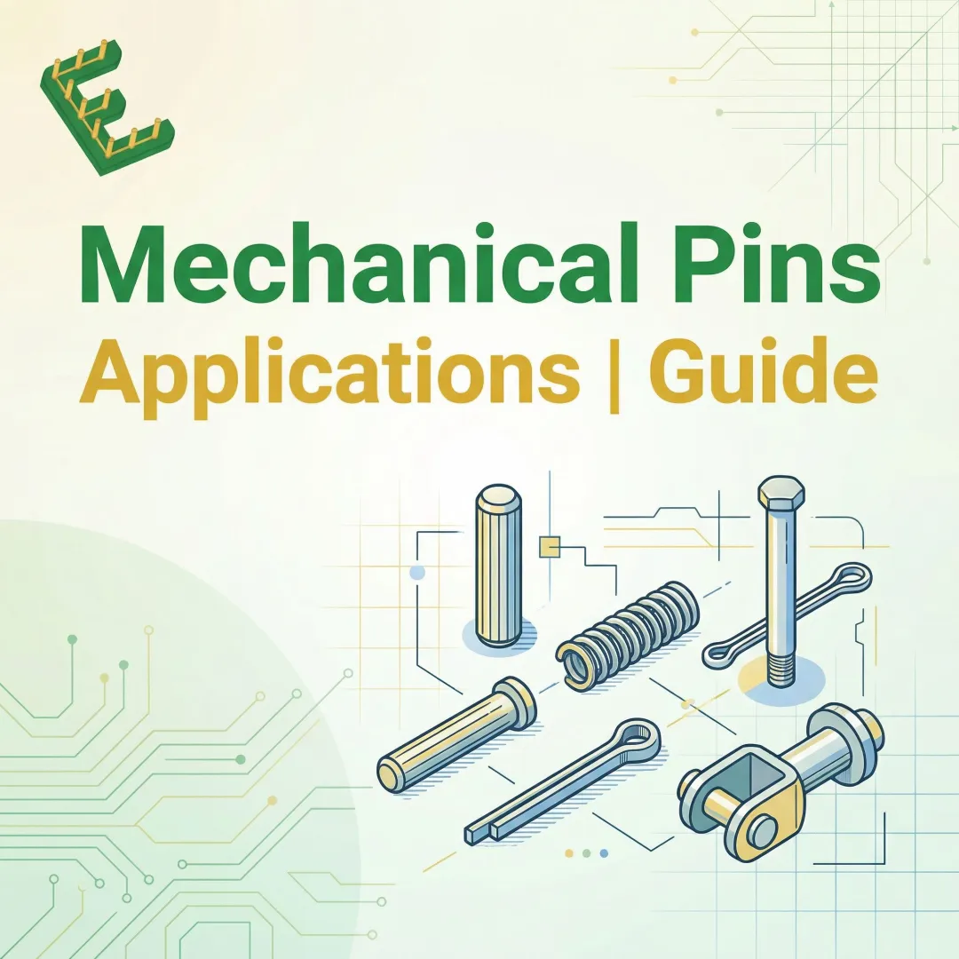
- Four main types exist: solid/rigid, spring-loaded (pogo), crimp-contact, and press-fit pins
- Crimp-contact pins dominate automotive and heavy equipment harnesses
- Press-fit pins excel in solderless PCB applications; pogo pins are built for high-cycle testing environments
- Selection depends on environment, assembly method, mating cycles, and current requirements
- Contact pin quality and dimensional consistency determine long-term reliability at scale
What Are Electrical Pin Connectors?
An electrical pin connector is a system in which a conductive metal pin (the male contact) inserts into a corresponding socket or receptacle to complete an electrical circuit. These connectors carry power, signals, or data between two points.
The connector housing — the plastic or metal body — holds and protects the contact pin, but it's the precision-formed metal pin that actually makes electrical contact. When discussing "pin connectors," we're referring to both the pin contact element and the system it operates within.
Pin connectors appear across virtually every sector of electronics manufacturing, including:
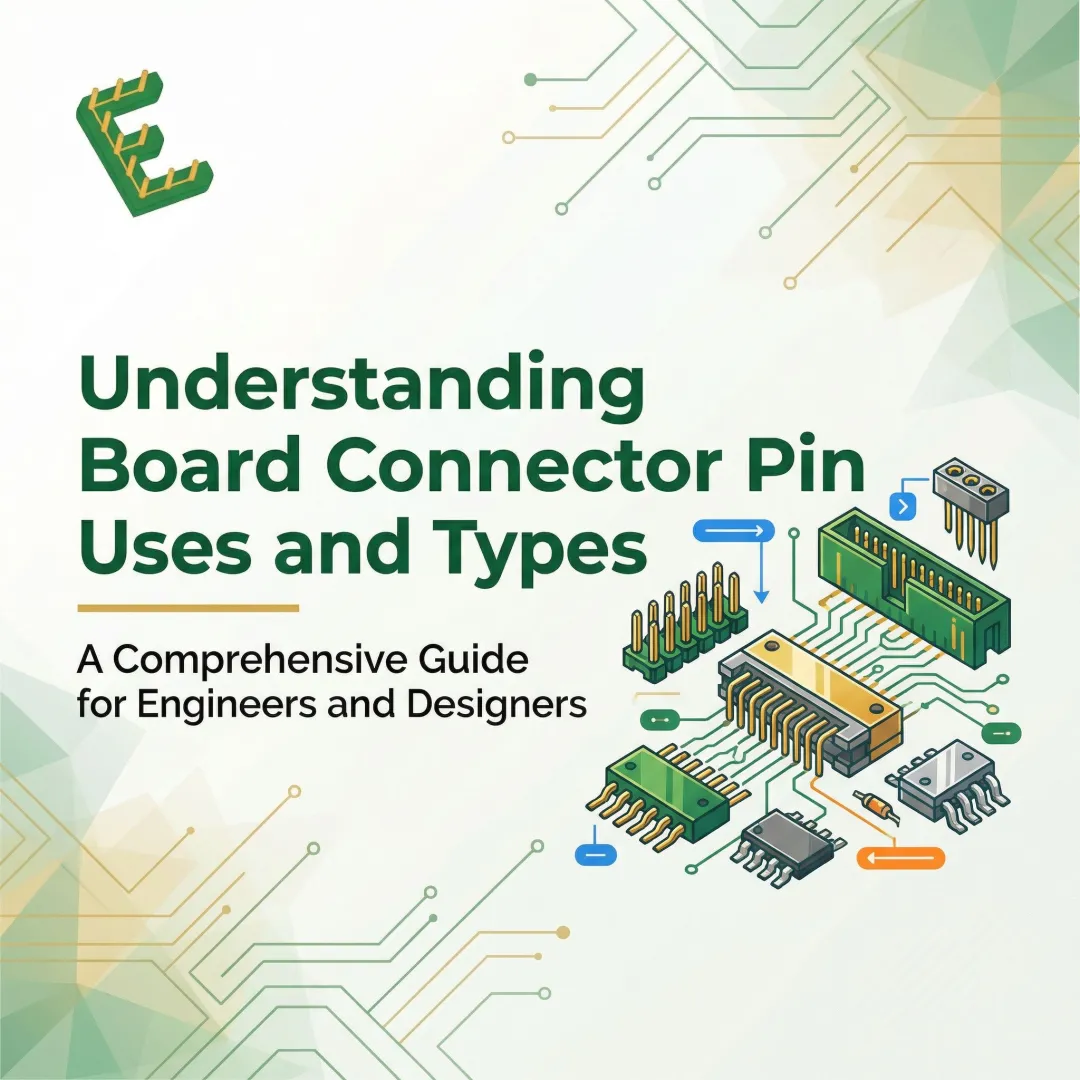
- PCB headers and circuit board assemblies
- Automotive wire harnesses
- Medical instruments and diagnostic equipment
- Industrial control systems
- Consumer electronics
Understanding the different types — and where each is used — helps engineers and procurement teams spec the right connector for the job.
Why Choosing the Right Pin Connector Type Matters
Different pin connector types are engineered for specific mechanical, electrical, and environmental conditions. Using a crimp-contact pin in a high-vibration automotive environment, for example, offers vibration resistance that a soldered connection cannot reliably match.
What goes wrong when the wrong type is selected:
- Intermittent connections
- Premature wear and contact failure
- Increased contact resistance and power loss
- Assembly failures during production
- Costly mid-production redesigns
According to documented field failure data, connector pin failures have triggered major automotive recalls. A 2023 Subaru recall affected over 8,400 vehicles due to corroded harness terminals, with an estimated 13% defect rate across affected units. A 2024 Genesis recall was initiated because incorrectly installed blanking pins allowed water ingress, leading to pin corrosion.
Both failures trace back to the same root cause: the physical pin didn't hold up under real-world conditions. Connector type selection is only half the equation — the dimensional consistency and material quality of the pin itself determines whether it performs as intended. A pin with loose tolerances or substandard material introduces contact resistance, shortens mating cycle life, and compounds defect risk across every unit in a production run.
Types of Electrical Pin Connectors
The right connector type depends on how the pin connects to a circuit, what environment it operates in, and what mechanical and electrical demands it must meet.
Each type differs in its contact-making method — with direct implications for assembly process, reliability, and cost. Pin geometry is where those differences are decided. Manufacturers like Electropin who specialize in custom contact pins can produce geometries tailored to any of these configurations.
Solid/Rigid Pin Connectors
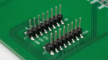
Solid or rigid pin connectors use a fixed, machined or cold-formed metal pin that inserts into a corresponding receptacle socket. The pin maintains its shape under normal mating forces and does not flex or compress during connection.
Where spring-loaded or compliant designs build in mechanical compensation, the rigid pin relies entirely on dimensional precision and a tight-fit socket. There is no tolerance for misalignment. Pin geometry directly determines connection quality.
Best suited for:
- PCB pin headers
- D-sub connectors
- IC sockets
- General-purpose wire-to-board and board-to-board applications
- Computers, consumer electronics, industrial control systems, and laboratory equipment
Key strengths:
- Simple to manufacture at high volume
- Cost-effective
- Highly predictable electrical performance when pin dimensions are consistent
- Compatible with a wide range of housing styles and pitch configurations
Common pitch dimensions include 2.54 mm (0.100"), 1.27 mm (0.050"), and fine-pitch options at 1.00 mm, 0.8 mm, and 0.5 mm. Current ratings vary by geometry, with standard PCB headers rated for approximately 4–6 A per pin and larger engineered pins handling up to 36 A.
Limitations: Rigid pins are susceptible to damage if mated under misalignment, offer no mechanical tolerance for vibration-induced movement, and depend entirely on pin and socket dimensional accuracy. Inconsistent pin geometry leads to loose fits, arcing, or failed contacts.
Spring-Loaded (Pogo) Pin Connectors
A pogo pin (spring-contact pin) consists of a plunger, a barrel, and a compressed spring. When the plunger contacts a mating surface, the spring compresses to maintain consistent contact force regardless of small positional variations or surface movement.
Rather than relying on a static fit, pogo pins actively maintain contact pressure through spring force — tolerating misalignment, surface irregularities, and repetitive connect/disconnect cycles without degrading the connection.
Best suited for:
- In-circuit testing (ICT) fixtures
- Battery contacts in consumer electronics and wearables
- Medical diagnostic equipment
- Docking stations
- Any application requiring frequent mating cycles or temporary contact with a flat pad
Key strengths:
- Extremely high mating cycle life (10,000 to over 1,000,000 cycles)
- Low insertion force
- Tolerance for surface variation and minor misalignment
- No need for a keyed socket
Manufacturer specifications show standard pogo pins rated for 2–9 A continuous current, with specialized high-current probes handling up to 150 A. Typical contact resistance is around 20 mΩ at mid-stroke.
Limitations: More complex and expensive to manufacture than rigid pins. Spring fatigue can reduce contact force over time in very high-cycle applications. Generally not suited for high-vibration environments where the spring may bounce. Not designed for high-current applications.
Crimp-Contact Pin Connectors
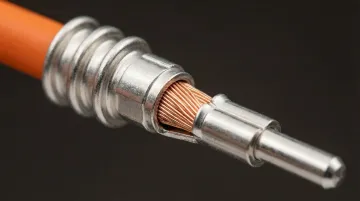
Crimp-contact pins are separate metal contacts that are crimped onto the stripped end of a wire, then inserted into a plastic connector housing. The crimp forms a gas-tight, friction-locked joint between the pin and the wire conductor.
The pin and wire are joined before the housing is assembled — not soldered or pre-attached. This separates the termination process from the connector body, simplifying complex multi-wire harnesses and allowing individual contacts to be replaced without scrapping the entire connector.
Best suited for:
- Automotive wire harnesses
- Agricultural and heavy equipment wiring
- Aerospace cable assemblies
- Any application requiring reliable connections in high-vibration or thermally cycled environments
Key strengths:
- High resistance to vibration and thermal cycling (the crimp creates a cold-welded joint with minimal oxide formation)
- Field-serviceable (individual pins can be extracted and replaced)
- Scalable to high-volume harness assembly
- Compatible with both sealed and unsealed housings
A "gas-tight" joint is the benchmark for crimp reliability. The terminal barrel is plastically deformed around the wire strands until all voids are eliminated — creating a metal-to-metal interface that blocks corrosive gases, moisture, and contaminants from degrading the connection over time.
Quality is governed by standards like IPC/WHMA-A-620 and SAE/USCAR-21, which specify crimp height, pull-out force requirements, and electrical resistance measurement methods.
Limitations: Requires proper crimping tooling and operator training to achieve consistent crimp quality. An under- or over-crimped joint significantly reduces pull-out strength and increases resistance. Crimped contacts are generally not reusable once removed.
Press-Fit (Compliant) Pin Connectors
Press-fit or compliant pins have a specially shaped zone — often called the "eye-of-the-needle" or compliant section — that is slightly oversized relative to the plated through-hole in a PCB. When pressed in, the pin deforms elastically to grip the hole wall and form a reliable, solderless connection.
The press-fit pin joins directly to the PCB without heat or additional materials. Elastic deformation of the compliant zone creates and maintains contact force — making the process faster, more consistent, and free of heat-related board damage.
Best suited for:
- Automotive ECUs and power modules
- Industrial motor drives
- Server backplanes
- Any PCB application where throughput, reliability, and the avoidance of thermal stress are priorities
Key strengths:
- Solderless process eliminates heat damage, flux contamination, and rework
- Highly consistent when pin geometry is tightly controlled
- Well-suited to automated high-volume assembly
- Meets demanding automotive reliability standards (e.g., AEC-Q100 environments)
The high normal force exerted by the compliant pin creates a gas-tight, cold-welded joint with the plated-through-hole, resulting in extremely low and stable contact resistance (typically below 0.1 mΩ). According to IEC 60352-5, the standard governing press-fit technology, press-fit connections are at least 10 times more reliable than soldered connections in high-vibration and thermal cycling environments.
Limitations: Press-fit connections are not easily reworkable — removing a pressed pin risks damaging the PCB through-hole plating. Pin and hole tolerances must be tightly controlled (typical finished hole size tolerance: ±0.05 mm), making consistent pin manufacturing critical. Not appropriate for low-volume prototyping where board reuse is needed.
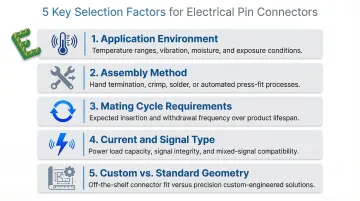
How to Choose the Right Electrical Pin Connector
The right choice depends on the application's specific requirements — not on which type is most familiar or most commonly used. Even within a chosen type, the precision of the contact pin geometry is a defining factor in long-term performance. Five factors drive that decision:
- Application environment: Evaluate vibration, shock, temperature range, and moisture or chemical exposure. Crimp-contact and press-fit pins outperform rigid pins in harsh environments; pogo pins suit controlled, high-cycle contact scenarios.
- Assembly method: Match pin type to connection style — wire-to-board favors crimp-contact, board-to-board favors solid rigid or press-fit, and temporary/test contact favors pogo. Whether assembly is automated or manual, soldered or solderless, should drive selection.
- Mating cycle requirements: High-cycle applications (test fixtures, wearables, docking stations) need spring-loaded designs with rated cycle lives. Low-cycle, semi-permanent connections (PCB headers, harness connectors) work well with solid or crimp-contact pins.
- Current and signal type: Higher-current applications require larger pin cross-sections and lower contact resistance. Signal-level applications prioritize consistent impedance. Confirm pin material and plating match the electrical requirements before finalizing a design.
- Custom vs. standard geometry: Standard catalog pins cover common configurations, but unique pitch, profile, length, or plating requirements call for custom contact pins. Manufacturers like Electropin produce pins to precise customer specifications — enabling designs that off-the-shelf options simply can't support.
What to Check Before Finalizing Your Pin Connector Selection
Avoid selecting a more complex pin type when a simpler one meets all requirements. Press-fit and pogo pins add cost and process complexity that is only justified when their specific performance advantages are needed. A solid rigid pin in a stable PCB application is often the right and most cost-effective answer.
Before committing to production, confirm that pin material, plating, and dimensional tolerances are fully specified. Contact resistance, corrosion resistance, and mating cycle life all depend on pin-level specs — not just connector housing ratings. Request the manufacturer's tolerance data and defect rate benchmarks and review them against your application requirements.
Also verify compatibility across two areas before sign-off:
- Mating component fit: Confirm the pin mates correctly with the socket, through-hole, or contact pad — dimensional mismatches cause intermittent failures that are difficult to trace after assembly.
- Assembly tooling: A crimp pin that requires tooling unavailable on your line, or a press-fit pin that doesn't match your PCB hole tolerance, will create production delays no matter how sound the connector design.
Conclusion
Electrical pin connectors — whether solid rigid, spring-loaded, crimp-contact, or press-fit — each serve distinct application needs. Selecting the wrong type introduces reliability failures, assembly problems, and unnecessary cost.
Beyond connector type, the precision and consistency of the contact pin itself determines whether the design performs to spec across thousands or millions of mating cycles. That's where manufacturing method matters. A pin produced with tight dimensional tolerances and zero scrap variance — from part one to part one million — holds the connection that everything else depends on. Getting both the connector selection and the pin quality right is what separates a design that works in the lab from one that holds up in production.
Frequently Asked Questions
What are the types of pin connectors?
The four main types are solid/rigid pin, spring-loaded (pogo) pin, crimp-contact pin, and press-fit (compliant) pin. Each differs in how contact is made: rigid pins rely on dimensional fit, pogo pins use spring force, crimp pins mechanically compress onto wires, and press-fit pins elastically deform into PCB holes.
What is the difference between male and female pin connectors?
The male connector carries the pin (the protruding contact), while the female connector holds the socket or receptacle that receives it. Both halves must be dimensionally matched for reliable contact — poor socket retention force or worn contact surfaces directly increase resistance and accelerate failure.
What materials are used in electrical contact pins?
Contact pins are typically made from copper alloys (brass, phosphor bronze, beryllium copper) for conductivity and formability. They are often plated with gold, tin, or nickel to reduce contact resistance and prevent corrosion. Gold offers the best performance for high-cycle and low-signal applications.
How do I choose the right pin connector for my application?
Start by evaluating these factors:
- Operating environment: vibration, temperature range, moisture exposure
- Assembly method: wire harness termination vs. direct PCB mounting
- Mating cycles: high-cycle applications require harder plating and tighter tolerances
- Signal type: low-current signals need lower contact resistance than power pins
From there, determine whether standard catalog geometry works or whether a custom pin profile is required.
What is the difference between crimp and press-fit pin connectors?
Crimp pins are crimped onto wire ends and inserted into a housing (used in wire harnesses), while press-fit pins are pressed directly into PCB through-holes without solder. Both are solderless but serve different assembly contexts: crimp for wire termination, press-fit for board attachment.
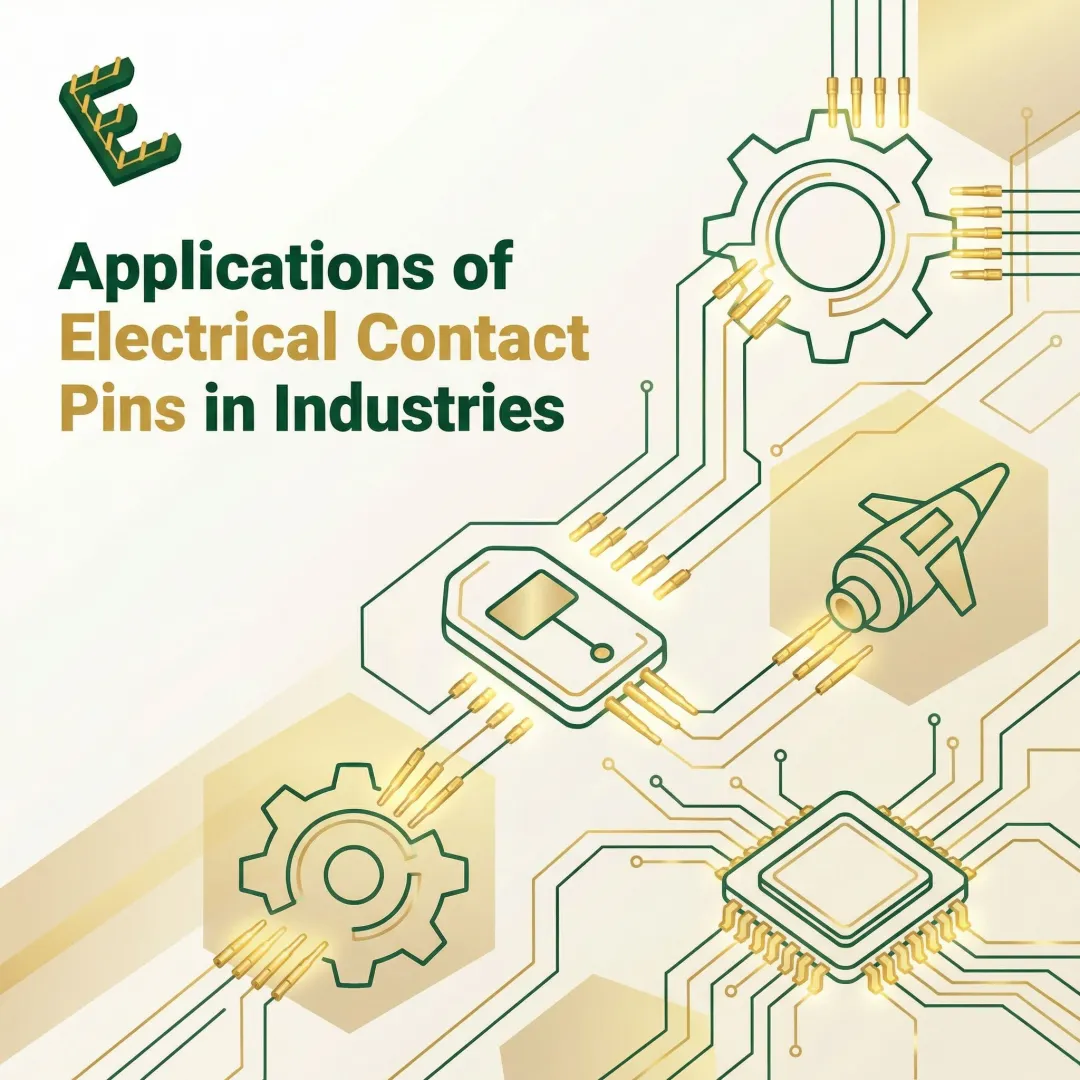
What industries use custom contact pins?
Custom contact pins are used across automotive, agricultural equipment, medical devices, computers and circuit boards, and industrial controls. Manufacturers like Electropin serve these sectors specifically because standard catalog pins rarely meet the geometry, plating, or volume requirements that high-reliability OEM applications demand.