Introduction
Mechanical pins show up in nearly every manufactured product — car door hinges, farm equipment linkages, circuit board connectors, medical devices. Despite that ubiquity, pin selection is one of the most underestimated decisions in early-stage design.
The wrong choice creates real costs: inconsistent part quality, premature assembly failure, warranty claims, and production delays. Getting the pin right early reduces costs, improves vibration resistance, and keeps electrical connections reliable across millions of cycles.
This guide covers the main types of mechanical pins, how they're used by function and industry, how to select the right one for your application, and how manufacturing method affects quality and consistency across production runs.
TLDR:
- Dowel, spring, taper, and cotter pins handle structural fastening; contact pins handle electrical connection
- Spring pins outperform solid pins in vibration-heavy applications by absorbing shock through controlled compression
- Contact pins demand tighter tolerances and material purity than most structural pins
- Cold forming produces more consistent parts at lower cost than machining, especially at high volumes
- Choosing the wrong pin type early in design leads to costly redesigns later
What Are Mechanical Pins?
Mechanical pins are cylindrical or shaped components used to fasten, align, connect, or transmit force between parts in an assembly. The term covers a wide family of hardware, from structural fasteners to electrical contact pins.
Two Primary Roles
Structural/Mechanical Pins hold or align physical components. Common examples include dowel pins that precisely locate mold halves, spring pins that create friction-fit hinges, and taper pins that lock gears onto shafts. Performance depends on:
- Shear strength
- Retention force
- Dimensional accuracy
Contact/Electrical Pins transmit electrical signals or current between connectors or circuit boards. Unlike structural pins, performance here turns on:
- Tight dimensional tolerances
- Material purity
- Surface finish
Within manufacturing contexts, "mechanical pin" refers to any precision pin whose performance depends on tight dimensional tolerances, material properties, and surface finish rather than threads or adhesives. That distinguishes pins from threaded fasteners like screws or bolts, which rely on helical threads for retention.
Types of Mechanical Pins
Solid Pins (Dowel Pins and Ground Pins)
Solid pins are cylindrical rods engineered to precise tolerances, typically ISO m6 fit class. They're manufactured from through-hardened or case-hardened steel with specified hardness ranges like 550–650 HV30.
Key characteristics:
- Require tight hole tolerances (often reamed or ground holes)
- Provide superior shear and bending strength
- Best for static, high-load applications
- Maintain precise alignment over time
When to use: High-precision assemblies like jigs, fixtures, and dies where repeatable positioning is critical and hole tolerances can be tightly controlled.
Spring Pins
Spring pins are hollow, self-retaining fasteners that compress upon installation, exerting radial force against the hole wall. Two main variants serve different load and environment requirements.
Slotted Spring Pins
C-shaped with a longitudinal slot. A general-purpose, low-cost option suited for light to medium retention in non-critical static assemblies. They accommodate wider hole tolerances (typically H12) than solid pins, eliminating costly reaming operations.
Coiled Spring Pins
Manufactured from a strip of metal coiled into a 2¼-turn cross-section, these pins deliver superior flexibility, shock absorption, and hole-damage prevention. Uniform radial tension along their full length makes them the right choice for vibration-prone assemblies and dynamic loading.
When to use: Coiled spring pins are preferred for most structural applications due to lower insertion forces and tolerance flexibility. Solid pins are chosen when a smooth surface, high bending strength, or precise hole location is required.
Taper Pins and Cotter Pins
Taper Pins
Solid pins with a uniform 1:48 taper (0.250 inches per foot per ASME B18.8.2). They lock hubs or levers onto shafts through a friction-based wedge effect — removable and reusable, which makes them well-suited for applications requiring precise indexing and regular serviceability.
Cotter Pins
Split pins inserted through a cross-drilled hole in a clevis pin, with legs bent in opposite directions to create a positive mechanical lock. They secure bolts, nuts, and clevis pins by deforming after insertion — suited for pivots, hinges, and linkages where quick disconnection matters.
Contact/Connector Pins
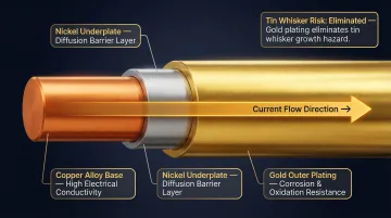
Unlike the mechanical retention types above, contact and connector pins are designed primarily to carry electrical current or signals. Precision-formed from copper alloy or brass, they appear in connectors, PCBs, medical devices, and automotive harnesses. Cold-forming processes are particularly well-suited here, since they produce the dimensional consistency these applications demand without introducing the surface variation that machining can cause.
Critical factors:
- Tolerances measured in microns to ensure reliable mating
- Material purity affects conductivity and durability
- Plating (gold, tin, nickel) impacts contact resistance and corrosion protection
- Governed by EIA-364 and IEC 60512 test standards, not mechanical pin standards
When to use: Any application requiring reliable, repeatable electrical connections. Performance depends on dimensional consistency, not just mechanical retention.
Comparison: When to Choose Each Type
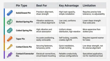
| Pin Type | Best For | Key Advantage | Limitation |
|---|---|---|---|
| Solid/Dowel | High-precision alignment, static loads | Superior shear strength, smooth surface | Requires tight hole tolerances |
| Slotted Spring | General-purpose retention, low cost | Accommodates wide hole tolerances | Lower strength than coiled pins |
| Coiled Spring | Vibration resistance, dynamic loads | Absorbs shock, prevents hole damage | More expensive than slotted pins |
| Taper | Indexing, removable shaft retention | Self-locking wedge fit, reusable | Requires matching tapered hole |
| Cotter/Clevis | Linkages requiring serviceability | Visual verification of retention | Deforms during installation |
| Contact/Connector | Electrical transmission | Reliable signal/current conduction | Requires micron-level tolerances |
Mechanical Pin Applications by Function
Alignment and Locating
Alignment pins precisely position two or more mating components—such as mold halves, engine blocks, or fixture plates—relative to each other before fastening.
Pin selection: Coiled spring pins are preferred for most alignment tasks because they accommodate slightly wider hole tolerances (H12 vs. h7), reducing machining cost. Solid ground dowels are reserved for the most precision-critical applications requiring micron-level repeatability.
Design rule: The receiving hole tolerance dictates pin type. If you can hold H12 tolerance with standard drilling, use coiled spring pins. If you need h7 tolerance for precision alignment, specify solid dowel pins and budget for reaming operations.
Hinge and Pivot
Free-fit hinges: The pin rotates freely in clearance holes, allowing smooth motion. Most designs use solid pins with polished surfaces.
Friction-fit hinges: The pin creates resistance to hold a component in position. Coiled spring pins dominate this application due to their uniform radial tension, which generates consistent frictional force against the hole walls until sufficient torque is applied to override it.
Design advantage: Manufacturer design guides provide radial force data by pin diameter, duty class (light, standard, heavy), and host material, allowing engineers to select the appropriate pin to achieve the desired hinge "feel."
Hub/Shaft Retention
Pins are pressed through a hub (gear, collar, or pulley) and into a shaft to transmit torque or prevent axial movement.
Dynamic load performance: Their flexibility absorbs vibrational loads and prevents hole elongation over time. As the pin flexes under dynamic loads, it distributes stress across its cross-section rather than concentrating it at the hole edge—preventing the progressive damage that causes solid pins to loosen.
Stop and Overtravel Prevention
Solid and spring pins are used as physical stops to limit the range of motion of actuators, levers, or rotating parts.
Critical design rule (60% retention rule): At least 60% of the pin's total length must be retained in the static component to ensure it won't be pushed out under load. This manufacturer guidance ensures secure retention and controls the diameter of the protruding free end.
Electrical Contact and Signal Transmission
Contact pins used in connectors, test sockets, PCBs, and medical devices must meet extremely tight dimensional tolerances to ensure reliable mating and consistent electrical resistance.
Base material and plating: Copper alloy base materials provide high conductivity. Gold plating over nickel underplate ensures low contact resistance and prevents corrosion. Tin plating is often avoided on contact surfaces to mitigate tin whisker growth risk.
Performance testing: IEC 60512 and EIA-364 test series govern contact resistance, insertion/removal force, durability over mating cycles, contact retention force, and resistance to shock, vibration, and corrosive environments.
Mechanical Pins Across Key Industries
Automotive
Automotive assemblies use multiple pin types simultaneously: dowel pins for engine and transmission alignment, cotter pins in steering and suspension linkages, and contact pins in wiring harnesses, ECU connectors, and sensor assemblies.
Dominant selection criterion: Vibration resistance. Coiled spring pins are strongly recommended for vibration-prone assemblies. Their design as functional springs lets them conform to the hole, absorb vibration, and maintain constant radial tension, preventing loosening and hole damage.
Standards:
- ISO 16750-3: Defines mechanical vibration and shock test methods used to validate component durability
- SAE J1455: Provides environmental definitions for heavy-duty vehicles
- Warranty exposure: In 2016, total warranty accruals in the US automotive sector reached $10.3 billion, with root causes including wrong or defective parts — a category that covers incorrect pin selection
Medical Devices and Connectors
Medical-grade contact pins must meet strict material biocompatibility standards and dimensional precision because unreliable connections in diagnostic equipment or implantable devices can have serious consequences.
Regulatory requirements:
- ISO 10993-1: Framework for assessing biological safety of materials that contact the human body
- RoHS (Directive 2011/65/EU): Restricts lead (Pb) to <0.1%, cadmium (Cd) to <0.01%, mercury (Hg) to <0.1%, and hexavalent chromium (CrVI) to <0.1% by weight
- REACH (EC No 1907/2006): Requires communication if SVHCs like lead exceed 0.1% by weight
Market growth: The medical connector market was valued at $1.64-$3.27 billion in 2023-2024 (depending on source), with projections reaching $2.45-$7.89 billion by 2030-2032, reflecting 7-11% annual growth.
Electronics and Circuit Boards
PCB connector pins, test probe pins, and IC socket pins create reliable electrical pathways. High-volume, high-consistency production is critical because a single out-of-tolerance pin in a connector can cause assembly failure at the board level.
Governing standards:
- IPC-A-610: Section 4.3 addresses acceptance criteria for connector pins, including press-fit and edge connector types
- IPC-2221: Provides hole tolerance and metallic coating requirements
- IEC 60512 / EIA-364: Test methods for contact resistance, insertion/removal force, durability, and retention
Failure impact: A 2025 study of 6,276 photovoltaic connectors found a 6.1% critical failure rate. Assemblies with pin engagement lengths outside optimal range had a 6.4 times higher failure rate, primarily from contact displacement. Dimensional consistency is not optional at scale.
Farm Equipment and Industrial Machinery
Heavy-duty machinery relies on robust pins (coiled spring pins, taper pins, and clevis pins) in linkages, hitches, PTO assemblies, and hydraulic fittings. The priority is shear strength and replaceability, as equipment often needs repair in the field with minimal downtime.
Key standard: ANSI/ASABE S625 establishes minimum strength and performance criteria for drawbar hitch pins, prescribing rigorous tests for fatigue endurance (1 million sinusoidal load cycles), shock/impact strength (100 cycles at higher load), and keeper force (50,000 load cycles).
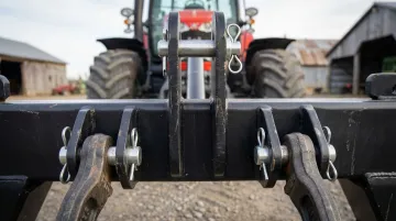
Typical applications: Clevis pins connect implements to tractors, with OEM manuals specifying required drawbar pin category based on implement power requirements to prevent failure.
How to Select the Right Mechanical Pin for Your Application
Key Evaluation Questions
Before finalizing a pin type, work through these questions:
- What is the pin's primary role—fastening, locating, pivoting, shear protection, or electrical contact?
- What static and dynamic loads will it experience? Coiled spring pins handle significant dynamic loading well due to their force-dampening and fatigue resistance.
- What is the host material—steel, aluminum, or plastic? This affects hole prep requirements and retention behavior.
- What environmental conditions apply? Moisture, corrosive chemicals, or extreme temperatures drive material selection (stainless vs. alloy steel) and coating choices.
- Is the assembly manual or automated, and at what production volume? Installation forces directly affect assembly speed and cost.
- Must the pin be removable and reusable? How many load cycles are expected over the product's lifetime?
General Selection Rule
For structural applications, the spring vs. solid pin decision comes down to a few key trade-offs:
| Criteria | Spring Pins | Solid Pins |
|---|---|---|
| Insertion force | Lower | Higher |
| Tolerance flexibility | Higher | Lower |
| Surface finish | Slotted/coiled | Smooth |
| Best for | Dynamic loads, tight tolerances | High bending strength, precise location, axial loads |
Electrical contact pins follow a separate specification path entirely. Material choice, plating, contact resistance, and environmental exposure all feed into that process independently of structural pin logic.
Design Timing
Pin selection should happen early in the design stage—not as an afterthought—because the choice affects host material, hole size, tolerance stack-up, and total assembly cost. Engaging a pin manufacturer during prototyping—before geometry, volume, and material are locked in—prevents the kind of late-stage redesigns that delay production and inflate cost.
Cost Impact of Wrong Selection
Incorrect pin selection contributes to the Cost of Poor Quality (COPQ), including increased scrap material, rework, production delays, warranty repairs, and recalls. If a defect requires 30 minutes of manual rework by a technician paid $40/hour, it results in a direct $20 labor cost per board—multiplied by thousands of units, this adds up fast across a production run.
How Custom Mechanical Pins Are Manufactured
Machining (Turning/Cutting from Rod Stock)
Material is cut to shape using turning or milling operations.
Limitations:
- Generates scrap material (40-70% material utilization, up to 65% scrap rate)
- Tools wear over time, causing dimensional drift from first part to last part
- Production rates relatively slow (2-20 parts per minute)
- Requires regular, costly retooling
When to use: Low-volume production, complex geometries requiring micron-level tolerances (±0.01 mm or tighter), or features unsuitable for cold forming.
Cold Forming (Die Rolling)
Material is pushed into a custom die and forced to conform to the die's shape through progressive forming stages. No cutting, no heat generation, no material removal.
Advantages:
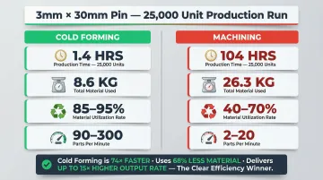
- Zero scrap: 85-95% material utilization, <1% scrap rate
- Dimensional consistency: Tools don't dull or change shape with heat, ensuring parts 1 and 1,000,000 match
- High production rates: 90-300 parts per minute (typical)
- Lower cost at volume: Break-even point typically 3,000-10,000 units
Real-world example: A case study analyzing a 3mm OD x 30mm pin showed total production time for 25,000 pieces was 1.4 hours for cold heading versus 104 hours for machining. Material consumption: 8.6 kg for cold heading versus 26.3 kg for machining.
Electropin's Automatic Die Rolling Technology
Electropin uses proprietary automatic die rolling cold-form technology to produce custom connector pins at up to five parts per second with a defect rate of just 1 in 600,000,000.
Raw wire or metal stock is progressively formed through a custom die without cutting or heating. Because tools don't dull, dimensional consistency is maintained across entire production runs — pins at the beginning of a batch match those at the end.
The material efficiency is direct: when you pay for five pounds of material, you get five pounds of pins. No scrap goes to the scrapyard. Unlike machined parts that often require leaded brass, automatic die rolling eliminates the need for leaded materials entirely — sidestepping REACH and RoHS compliance concerns from the start. Electropin can begin manufacturing in as little as two weeks after die creation, with flexible batch delivery schedules.
Compliance for Engineers
Engineers specifying custom pins for medical, automotive, or electronics applications should confirm three things with any supplier: manufacturing process, scrap rate, and how dimensional consistency is maintained from the first part to the millionth. The answers directly affect compliance exposure, unit cost at volume, and whether the parts you receive in batch 50 match the ones you qualified in batch one.
Frequently Asked Questions
What are mechanical pins?
Mechanical pins are cylindrical or shaped components used in assemblies to fasten, align, join, stop movement, or transmit electrical signals. The term covers both structural fastener pins (dowel, spring, taper, cotter) and electrical contact pins used in connectors and circuit boards.
What are the most common types of mechanical pins?
The main categories include:
- Solid/dowel pins — high-precision alignment in static assemblies
- Slotted spring pins — general-purpose retention across a wide range of fits
- Coiled spring pins — vibration resistance and dynamic load absorption
- Taper pins — shaft retention with easy removal
- Cotter pins — linkage security in low-speed joints
- Contact/connector pins — electrical signal and power transmission
Each has a distinct best-use case.
What is the difference between solid pins and spring pins?
Solid pins rely on material displacement for retention and offer high shear strength for static loads. Spring pins flex to accommodate hole tolerances and absorb dynamic loads, making them more versatile for most structural applications. Coiled spring pins can meet or exceed the shear strength of solid pins while also preventing hole damage.
How do I choose the right mechanical pin for my application?
Evaluate the pin's function, load type (static vs. dynamic), host material, environment, installation method, and production volume. Spring pins suit dynamic applications; solid pins suit high-precision static loads. For electrical applications, specify contact pins with appropriate material and plating.
What industries use mechanical pins most?
The highest-volume users each have distinct requirements:
- Automotive — vibration resistance across connectors and chassis components
- Medical devices — biocompatibility and tight dimensional tolerances
- Electronics/PCB manufacturing — consistency across high-volume production runs
- Heavy industrial and farm equipment — shear strength and field serviceability
What are contact pins used for?
Contact pins are precision-formed electrical components used in connectors, circuit boards, test sockets, and medical devices to create reliable, repeatable electrical connections. Performance depends on tight dimensional tolerances, material purity, and appropriate surface plating — not mechanical retention alone.