Introduction
In 2019, a recall of over 100,000 pacemakers traced back to a single point of failure: corroded contact pins in the device's connector assembly. These tiny conductive elements—each smaller than a grain of rice—had degraded under repeated sterilization cycles, creating intermittent electrical faults that put patients at risk. This incident illustrates a hard truth about modern engineering: when a contact pin fails, the entire system fails with it.
An electrical contact pin is the conductive element within a connector that creates the physical point of electrical contact, transferring current and signals between mated components. This article explores how these components serve four major industrial sectors—automotive and transportation, medical devices, electronics and circuit boards, and agricultural and heavy equipment. It also covers what engineers and procurement teams should evaluate when specifying or sourcing them for mission-critical applications.
What Are Electrical Contact Pins?
An electrical contact pin is the conductive element within a connector system that provides a separable electrical connection. The IPC-T-50 standard defines a connector contact as "the conducting member of a connecting device that provides a separable connection."
Unlike the connector housing (which provides mechanical structure) or the wire termination (which anchors the conductor), the pin handles three critical functions: maintaining mechanical mating force, transferring electrical current with minimal resistance, and preserving signal integrity across mating cycles.
The pin's geometry and material properties determine whether a connector meets its rated specifications. A stable, gas-tight contact interface with low resistance minimizes micro-movements (fretting) that introduce noise in data signals or voltage drops in power circuits. Standardized tests such as IEC 60512-2-1 verify contact resistance performance across mating cycles.
Manufacturing Methods: Machined vs. Cold-Formed
Two primary manufacturing approaches dominate contact pin production, each with distinct implications for quality and cost:
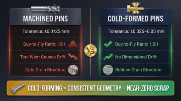
Machined Pins (Turned from Bar Stock):
- Material is removed through cutting to achieve final shape
- Achieves tight tolerances: ±0.0125 mm standard, down to ±0.0025 mm with precision ground rod
- Cuts through material grain structure, creating potential stress concentration points
- High material waste with buy-to-fly ratios of 10:1 or higher
- Tool wear causes dimensional drift across production runs
Cold-Formed Pins (Die-Rolled from Wire):
- Metal shaped at room temperature using compressive force through dies
- Typical tolerances: ±0.025 mm to ±0.05 mm
- Refines and aligns grain structure, increasing tensile strength and fatigue resistance
- Minimal scrap with buy-to-fly ratios approaching 1.5:1
- Tools maintain consistent geometry from the first part to the millionth — no dimensional drift
The trade-off is straightforward: machining achieves tighter initial tolerances but introduces tool-wear drift and significant material waste. Cold-forming sacrifices some dimensional range in exchange for consistent geometry, near-zero scrap, and stronger material properties through work hardening.
Base Materials and Plating Options
Contact pins are typically manufactured from copper alloys chosen for their balance of conductivity, formability, and mechanical properties:
Common Base Materials:
- Brass (C36000): Excellent machinability, moderate conductivity (26% IACS), cost-effective for standard applications
- Phosphor Bronze: Higher spring force and fatigue resistance than brass
- Beryllium Copper: Premium choice for high-cycle applications requiring maximum spring force
Plating Finishes:
- Gold (Au): Lowest contact resistance, no oxidation, excellent fretting resistance; typically 0.8 µm hard gold over 1.3 µm nickel underplate; rated for 100–1,000+ mating cycles
- Tin (Sn): Cost-effective for moderate environments, prone to oxidation in high-humidity or high-cycle applications
- Silver (Ag): High conductivity (105% IACS) suited for RF and power contacts, though susceptible to tarnishing without protective topcoats
Material selection must also account for regulatory compliance. The EU RoHS Directive 2011/65/EU restricts lead to 0.1% by weight. Exemption 6(c) currently allows copper alloys with up to 4% lead for free-cutting brass, but that exemption expires December 31, 2026. Manufacturers sourcing leaded brass pins today face a hard compliance deadline — one reason OEMs across automotive, medical, and electronics are already shifting to lead-free formulations.
Automotive and Transportation Applications
Modern vehicles represent one of the most demanding environments for electrical contact pins. A single passenger car contains hundreds of connector assemblies—engine control units, body control modules, transmission sensors, lighting assemblies, and safety-critical systems like airbags and ABS.
Each connector may house dozens of contact pins, creating thousands of electrical contact points that must perform reliably over the vehicle's entire service life—often 10-15 years in harsh conditions.
Environmental Stressors in Automotive Applications
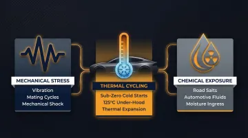
Automotive contact pins face a convergence of environmental challenges that few other applications must withstand simultaneously:
Mechanical Stress:
- Sustained vibration from engine operation and road surface irregularities
- Constant mating/unmating cycles during vehicle assembly and field service
- Mechanical shock from impacts and rough handling
Thermal Cycling:
- Sub-zero cold starts in winter climates
- Under-hood temperatures exceeding 125°C
- Rapid temperature transitions creating thermal expansion stress
Chemical Exposure:
- Corrosive road salts in northern climates
- Automotive fluids (oil, coolant, brake fluid)
- Humidity and moisture ingress
These stressors are validated through industry standards like SAE/USCAR-21 Rev. 4, which specifies accelerated environmental exposure testing including 72 thermal shock cycles from -40°C to +125°C followed by temperature/humidity cycling at 65°C/95-98% RH. Contact resistance must remain within specified limits after this exposure sequence.
Electrification and High-Density Connector Demands
The automotive industry's shift toward electrification has significantly increased both the quantity and complexity of contact pin applications. Electric and hybrid vehicles introduce new high-voltage systems for batteries, inverters, and charging interfaces, alongside extensive low-power signal networks for Battery Management Systems (BMS) that monitor individual cell voltages and temperatures.
According to MarketsandMarkets, the EV connector market was valued at $2.73 billion in 2025 and is projected to grow at 18.2% CAGR. Three factors are driving this growth:
- Electrification: High-voltage battery systems and charging interfaces
- ADAS (Advanced Driver-Assistance Systems): Cameras, radar, LiDAR sensors generating vast data volumes requiring high-speed, shielded connectors
- Zonal E/E Architectures: Consolidation of vehicle functions into powerful central computers with ECUs requiring connectors with over 250 positions
A luxury vehicle can contain 80-150 ECUs, with high-performance units accommodating several hundred wire connections via high-density connectors. Even a component as simple as an LED headlamp can contain up to 120 terminals.
This pin-count proliferation demands manufacturing processes that deliver consistent dimensional accuracy across production runs. Automated vehicle assembly lines cannot tolerate even marginal dimensional variation that causes insertion failures or intermittent contact.
Beyond Passenger Vehicles
That same demand for dimensional consistency extends beyond passenger cars. Commercial trucks, rail equipment, and marine electronics share the core automotive requirements but often need additional protection. IP67/IP68-rated sealing becomes essential for underbody and exterior applications where moisture and contaminant ingress is unavoidable. Telematics systems—OBD ports, GPS tracking modules, fleet management hardware—must support regular connect/disconnect cycles by field technicians while maintaining signal integrity in cab or underbody environments exposed to temperature extremes and vibration.
Medical Device Applications
Medical-grade electrical contact pins appear throughout clinical environments in equipment where reliability directly impacts patient safety. Diagnostic machines (EEG, ECG, EMG), surgical handpieces and power tools, therapeutic devices, imaging equipment, and portable patient monitors all depend on contact pins that must maintain electrical performance under conditions that would destroy standard industrial components.
The Sterilization Challenge
Reusable surgical instruments and clinical equipment must withstand repeated sterilization cycles without degradation. Steam autoclave sterilization—the most common and aggressive method—exposes contact pins to high-pressure saturated steam at 121-134°C. This environment creates unique failure modes not encountered in other industries.
Gold plating is generally preferred for autoclave compatibility due to its chemical inertness and oxidation resistance at high temperatures. The primary failure mechanism, however, is not gold degradation but galvanic corrosion of the underlying nickel barrier layer.
When gold plating is thin, porous, or mechanically damaged, the autoclave's heat and moisture accelerate nickel oxidation. The resulting nickel oxide increases contact resistance and can cause electrical opens.
Connector manufacturers provide system-level qualification data as benchmarks. The Eaton/Souriau JMX series is certified to withstand up to 200 steam autoclave cycles at 134°C, while LEMO medical connectors are rated for 500 autoclave cycles. These cycle ratings depend on both plating quality and the connector's overall mechanical design protecting the contact interface.
Alternative sterilization methods present different material challenges. Sterrad hydrogen peroxide plasma and chemical disinfectants can attack certain plating materials, while gamma radiation can degrade polymers in the connector housing that mechanically support the pins.
High Mating-Cycle Requirements
Medical connectors experience repeated connect/disconnect cycles during clinical use and device reprocessing. A surgical handpiece might be connected, used in a procedure, disconnected for cleaning, sterilized, and reconnected dozens of times per week. This creates cumulative mechanical wear on the contact interface.
Dimensional consistency is where tolerance control directly affects patient outcomes. A contact pin even 0.05 mm under nominal diameter may make adequate contact initially, then develop intermittent faults as the mating spring relaxes over repeated cycles. In life-critical monitoring equipment like ECG or pulse oximetry, intermittent contact can trigger false alarms or fail to detect actual patient distress.
Regulatory Context and Traceability
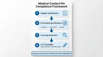
Medical device manufacturers operate under the FDA Quality Management System Regulation (21 CFR Part 820), which incorporates ISO 13485:2016. This framework requires component traceability and supplier control. Manufacturers must establish risk-based systems for controlling suppliers of critical components like contact pins, including:
- Formal supplier qualification processes
- Detailed purchasing specifications (materials, dimensions, plating)
- Incoming inspection procedures
- Lot traceability linking specific contact pin batches to finished devices
This traceability is crucial for managing nonconforming products, investigating field failures, and executing effective Corrective and Preventive Actions (CAPA). Contact pin suppliers serving the medical device industry must demonstrate full material certifications, REACH/RoHS compliance, and ideally near-zero defect rates to pass these quality system requirements.
Miniaturization in Wearables and Implantables
The wearable medical device market is projected to grow at 25.53% CAGR, driving demand for miniaturized contact pins. According to MarketsandMarkets, the medical device connectivity market reached $1.64 billion in 2024 with a forecast CAGR of 7.1% through 2030.
Wearable and implantable devices face severe spatial constraints. Connector manufacturers like Fischer and TE Connectivity have responded with solutions such as the Fischer MiniMax™ Series (30 contacts in a ø14 mm connector) and ultra-low-profile FPC connectors.
These miniaturized designs demand tighter manufacturing tolerances, smaller contact geometries, and fine-pitch solutions to support advanced sensors and growing data bandwidth requirements. Biocompatibility and lead-free material compliance are non-negotiable across all of them.
Electronics, Computers, and Circuit Board Manufacturing
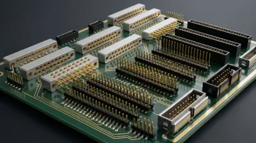
Electrical contact pins serve several distinct roles in PCB and electronics manufacturing:
- Interface between connector housings and circuit boards (through-hole or SMT mounting)
- Test point contacts in in-circuit testing (ICT) fixtures
- Contacts in edge-card and board-to-board connectors for servers, desktops, and embedded computing systems
Pitch Miniaturization and Tolerance Demands
The electronics industry has pursued relentless miniaturization, driving connector pitch (center-to-center spacing between pins) from legacy 2.54 mm standards to 1.27 mm, 1.0 mm, and now common sub-1 mm micro-pitches of 0.8 mm, 0.5 mm, and even 0.4 mm for high-density systems.
This trend imposes much stricter manufacturing tolerances. According to IPC-2221A, a press-fit pin requires hole tolerance of approximately ±0.05 mm—twice as tight as the ±0.10 mm tolerance for standard plated through-holes. For 0.4 mm pitch connectors, datasheets specify pad pitch tolerances of ±0.02 mm to ensure proper alignment and soldering.
As pitch shrinks, the margin for defects drops in turn. A contact pin with 0.03 mm dimensional variation might perform acceptably in a 2.54 mm pitch connector but will cause catastrophic misalignment in a 0.5 mm pitch application.
This reality creates strong preference for suppliers who can demonstrate consistent quality across very large production runs — the kind of consistency that cold-form manufacturing methods are specifically built to deliver.
Insert-Molding and Press-Fit Applications
Circuit board and molded plastic parts manufacturing represents a distinct application segment where contact pins are insert-molded or press-fit into plastic connector bodies. For this automated assembly process to work reliably, every pin must meet exact dimensional specifications.
Even minor variation causes insertion failures, broken molds, or poor retention. A pin with diameter 0.05 mm oversize may jam in the insertion tooling, while an undersize pin will have inadequate retention force and may pull out during connector mating. High-volume electronics assembly lines cannot afford downtime for manual rework or tooling adjustments caused by inconsistent pin dimensions.
Consumer vs. Industrial Computing Requirements
Consumer electronics (laptops, gaming hardware, networking equipment) and industrial computing (PLCs, industrial PCs, ruggedized terminals) specify different pin requirements. The table below summarizes the key differences buyers should communicate when sourcing:
| Requirement | Consumer Electronics | Industrial Computing |
|---|---|---|
| Primary priority | Cost and compact size | Durability and vibration resistance |
| Mating-cycle rating | 100–500 cycles | 100,000 to >1,000,000 cycles |
| Vibration testing | Standard | Up to 25g |
| Environmental protection | Standard | IP67/IP68 |
| Typical plating | Tin over brass | Gold over beryllium copper |
Buyers should communicate these priorities clearly when sourcing contact pins. A pin optimized for consumer applications may use cost-effective tin plating and standard brass, while industrial applications may require gold plating over beryllium copper for maximum cycle life and vibration resistance.
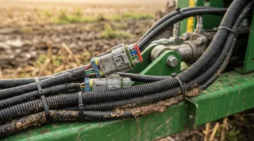
Agricultural and Heavy Equipment Applications
Farm equipment and heavy machinery operate in some of the most hostile environments for electrical contacts. Tractors, harvesters, irrigation control systems, and construction machinery face constant vibration, wide temperature swings (-40°C to +85°C), and exposure to moisture, dust, fertilizers, and pesticides. Yet these systems increasingly rely on sophisticated electronics for GPS guidance, precision agriculture sensors, and automated control systems.
Unique Environmental Demands
Agricultural connectors must remain reliable over years of seasonal use with minimal maintenance. Unlike automotive applications where scheduled service intervals provide opportunities for inspection and replacement, farm equipment may operate for months in remote fields before returning to a maintenance facility.
The global precision farming market was valued at $11.67 billion in 2024 with a projected CAGR of 13.1%, driven by adoption of GPS-guided auto-steering, variable-rate application systems, and yield monitoring technology. Each of these systems depends on connector assemblies that must withstand environmental extremes.
Key Challenges:
- Constant mechanical stress from diesel engines and rough terrain
- Exposure to mud, fertilizer salts, and pesticide chemicals
- Rain, irrigation spray, and condensation driving moisture ingress
- Daily temperature swings from cold overnight lows to midday heat
- Field connections made without precision tools or controlled conditions
Fretting Corrosion in High-Vibration Environments
Fretting corrosion is a leading cause of contact-pin failure in agricultural and heavy equipment applications. It occurs when vibration or thermal cycling causes micro-movements at the contact interface. This mechanical motion wears away protective plating, exposing base metals that oxidize — and the resulting oxide buildup increases electrical resistance, leading to intermittent signals or open circuits.
Gold plating resists fretting corrosion best because it doesn't oxidize and holds low contact resistance even after mechanical wear. Cost constraints in agricultural applications often favor tin or silver plating instead, making pin dimensional consistency even more critical — consistent geometry ensures adequate contact normal force is maintained throughout the service life.
IP-Rated Sealing and Long-Term Reliability
Agricultural applications frequently require IP67 or IP68 environmental protection to prevent moisture and contaminant ingress. While the connector housing provides the primary seal, the underlying contact pins must be dimensionally consistent so the housing can maintain its rated protection.
A batch of pins with ±0.10 mm diameter variation can prevent proper sealing or create uneven mechanical stress that degrades seals over time. Dimensional consistency across high-volume production runs isn't a nice-to-have in this segment — it's what keeps a $500,000 harvester running through a critical planting window. Manufacturers supplying this market need contact pins held to tight tolerances, part one through part one million, to meet both IP ratings and long-term field reliability standards.
What to Look for in a Contact Pin Manufacturer
Selecting a contact pin supplier requires evaluating both manufacturing capability and practical procurement factors. The choice impacts not just initial unit cost but total cost of ownership across the product lifecycle.
Manufacturing Quality Indicators
Defect Rate and Process Capability
Top manufacturers target a process capability index (Cpk) above 1.67, corresponding to defect rates well below 50 parts per million. Automotive sector suppliers routinely hold this standard.
Manufacturing method drives consistency. Cold-forming processes maintain precise geometry because material is shaped rather than cut — tools don't dull or shift with heat. Machining faces inherent dimensional drift as cutting tools wear; the first pin in a run will measurably differ from the ten-thousandth unless tools are replaced frequently.
Before committing to a supplier, ask:
- What is your demonstrated defect rate across full production runs (not just first-article samples)?
- How do you verify dimensional consistency throughout a batch?
- Can you provide Cpk data from recent production lots?
Material Utilization and Total Cost of Ownership
Buy-to-fly ratio directly impacts effective per-unit cost. Cold-forming processes achieve BTF ratios approaching 1.5:1 — minimal material becomes scrap. Machining processes often run 10:1 or higher, meaning a significant portion of expensive raw material ends up as waste.
When comparing quotes, calculate total cost across:
- Material cost adjusted for utilization efficiency
- Scrap and rework rates
- Tooling and retooling costs over the production lifecycle
- Quality inspection costs to catch dimensional variation
A supplier with 10% higher nominal per-piece pricing but near-zero scrap may deliver lower effective cost than one with cheaper pricing and high material waste.
Practical Procurement Factors
Four factors determine whether a supplier will actually work for your program long-term:
Lead time and scalability. Some manufacturers deliver initial batches in two weeks when raw materials are available; others need 8-12 weeks for tooling and setup. More important than initial lead time is flexibility — a supplier should be able to ramp from 10,000 units per month to 100,000 without costly retooling or quality degradation.
Minimum order quantities. High-volume production processes optimize for scale. Clarify MOQs upfront and ensure your volume requirements align with the supplier's process — mismatches here lead to inflated per-unit costs or delivery delays.
Compliance documentation. Medical and automotive OEM customers require certificates of analysis, REACH/RoHS compliance declarations, and lot traceability records. Verify the supplier can produce these and has experience with your industry's specific regulatory requirements.
Design collaboration. The strongest supplier relationships start before manufacturing. Engineers who will review your pin geometry, flag manufacturability issues, and optimize for both performance and cost reduce risk significantly — especially for new designs. Ask whether their team collaborates during design or only manufactures to print.
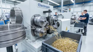
Example: Automatic Die Rolling Technology
Electropin's automatic die rolling technology shows what high-precision contact pin manufacturing looks like in practice. The cold-forming process produces custom contact pins at speeds up to five pins per second with a defect rate of 1 in 600,000,000 — tools maintain consistent geometry throughout because they never dull or shift with heat.
The process eliminates material waste: when you pay for five pounds of raw material, you receive five pounds of finished pins with zero scrap. This contrasts with machining, where significant material becomes swarf. Additionally, automatic die rolling doesn't require leaded brass, simplifying REACH and RoHS compliance.
Lead times can be as short as two weeks for initial batches when raw materials are available, and the process scales dynamically as production needs change without costly retooling.
Frequently Asked Questions
What materials are electrical contact pins typically made from?
Most contact pins are manufactured from copper alloys—brass, phosphor bronze, or beryllium copper—chosen for their balance of electrical conductivity and mechanical formability. These base materials are then plated with gold, tin, or silver to enhance corrosion resistance and contact performance. Lead-free alloy options are available for applications requiring REACH/RoHS compliance.
How do electrical contact pins differ from the connector itself?
The connector is the complete assembly including the housing, locking mechanism, and wire termination system. The contact pin is the individual conductive element inside that makes the actual electrical connection when mated. Pin quality determines whether the connector meets its rated current capacity, signal integrity specs, and mating-cycle durability.
Why does pin manufacturing method matter for industrial applications?
Machined pins can drift in dimension as cutting tools wear over a production run, leading to inconsistency between the first and millionth part. Cold-formed or die-rolled pins maintain consistent geometry throughout production because material is shaped under pressure rather than cut, and tools don't degrade. In automated assembly and high-reliability applications, that dimensional variation translates directly to insertion failures and intermittent contact.
What makes electrical contact pins suitable for medical or automotive use?
Suitability depends on tight dimensional tolerances (typically ±0.025 mm or better), correct material and plating for the environment, compliance with standards like REACH/RoHS or USCAR-21, and a verified low defect rate. Medical applications additionally require full traceability documentation across production volumes.
How many contact pins does a typical automotive or industrial device use?
A modern passenger vehicle contains hundreds of connector assemblies with thousands of individual contact points—luxury vehicles can have 80–150 ECUs, and a single LED headlamp may hold up to 120 terminals. Industrial equipment varies widely, but precision agriculture machines increasingly rely on dozens of connectors for GPS, sensor networks, and automated controls.
What should I specify when ordering custom contact pins?
Provide pin diameter and length, pitch (if part of a connector array), base material and plating type, current and voltage rating requirements, quantity and delivery schedule, and any relevant compliance requirements (REACH/RoHS, medical device standards, automotive qualifications). A manufacturer with deep design experience can review your geometry early in the process to flag manufacturability issues and reduce per-unit cost before production begins.