PCB pin removal is a recurring task across electronics repair, prototyping, and manufacturing. Yet most damage occurs not from lack of skill, but from applying the wrong technique to the wrong pin type. A connector-housed terminal requires a completely different approach than a soldered through-hole pin, and confusing the two is the fastest way to destroy a board.
This guide covers the key pin types you'll encounter, the right tools for each, a step-by-step removal process that protects both pin and board, common mistakes that cause damage, and how to decide when a pin should be replaced rather than reused.
Key Takeaways
- PCB pins use either locking latches or solder joints — and each type requires a different removal method
- Always power down the board and use ESD-safe tools before starting
- For connector pins, use the correct extraction tool to depress the locking lance before pulling—never yank the wire
- For soldered pins, clear all solder with flux, a soldering iron, and a desoldering pump before pulling the pin
- Inspect every pin after removal; replace any showing deformation, cracks, or corrosion
Understanding PCB Pin Types and Why the Removal Method Matters
Not all PCB pins come out the same way. Applying the wrong removal method to the wrong pin type is the primary cause of board damage — so identifying what you're working with before you start is the most important step.
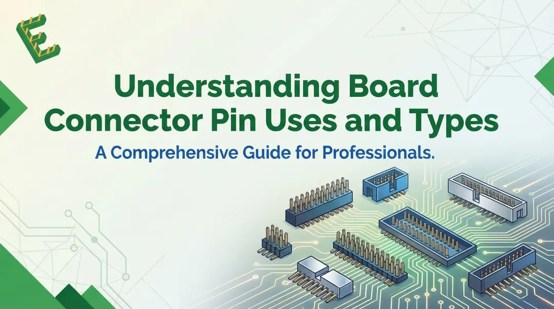
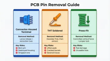
Connector-Housed Terminal Pins
These are metal pins crimped to a wire and inserted into a plastic housing body. They're locked in place by either a terminal lance (a flex tab on the metal pin itself) or a housing lance (a plastic finger inside the housing body).
The lock must be released before any extraction is attempted. Pulling without disengaging the lance bends the pin at the crimp point, destroys the housing, and can strip the wire entirely.
THT Soldered Pins
These pins are inserted through drilled holes in the PCB and soldered in place, forming a permanent electrical connection. They cannot be extracted mechanically: the solder joint must be melted and cleared first. Forcing a soldered pin out without removing the solder lifts pads, cracks barrels, and severs traces.
Press-Fit Pins
These rely on an interference-fit mechanism where a spring-loaded zone grips the plated hole without solder. Removal requires controlled vertical force and a proper extraction tool to avoid pad damage. According to IEC 60352-5, extracted press-fit pins should not be reused, though the plated-through hole can be reused up to three times.
Here's a quick reference for the three pin types:
| Pin Type | Removal Method | Key Risk If Done Wrong |
|---|---|---|
| Connector-Housed Terminal | Lance release + extraction tool | Bent pin, destroyed housing, stripped wire |
| THT Soldered | Desolder first, then extract | Lifted pads, cracked barrels, severed traces |
| Press-Fit | Controlled vertical force, proper tool | Pad damage, unusable hole |
Tools You'll Need Before You Start
For Connector-Housed Pin Removal
- Pin extraction tool kit - Tubular extractors for round pins, blade/shovel tools for flat pins (matched to your connector series)
- ESD-safe tweezers - For handling small components
- Bright light source or magnifier - Essential for identifying the locking mechanism
Improvised tools like paper clips and sewing needles directly cause plastic housing deformation. Always use the extraction tool specified for the connector series and pin gauge.
For Soldered Pin Removal
- Temperature-controlled soldering iron - Essential for managing heat dwell time
- Rosin-based flux - Reduces surface tension and prevents oxidation
- Desoldering pump or wick braid - For clearing molten solder from holes
- PCB support fixture - Holds the board stable during extraction
- Hot air rework station - Required for multi-pin connectors; speeds up removal and reduces thermal stress
Safety Checklist Before Starting
- Confirm power is disconnected and capacitors have discharged
- Use an ESD wrist strap when working on sensitive boards (ANSI/ESD S20.20 compliance)
- Work in adequate lighting with the PCB secured
How to Remove PCB Pins Without Damage
The single most important rule: match the technique to the pin type. Rushing or guessing the approach causes the majority of pin and board damage in real-world rework.
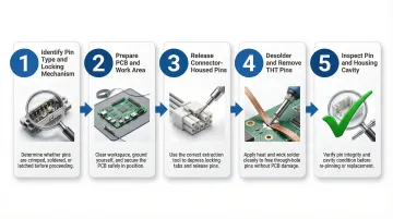
Step 1: Identify the Pin Type and Locking Mechanism
Before touching any tool, visually inspect whether the pin is inside a plastic connector housing or soldered directly to the board.
For connector-housed pins:
- Determine if the locking lance is on the terminal (metal tab visible on the pin) or on the housing (a plastic finger inside the cavity)
- Check the connector documentation or manufacturer datasheet if unsure
- Inserting from the wrong side with the wrong tool is a common mistake
For soldered pins:
- Confirm all joints are visible and accessible
- Identify how many pins must be cleared before extraction
Step 2: Prepare the PCB and Work Area
Support the PCB on a stable, non-conductive surface or fixture; a board that flexes under pressure risks trace delamination.
For soldered pins, apply rosin flux to each joint before heating. Flux lowers the melting temperature, reduces heat dwell time (which should not exceed 15–20 seconds at peak temperature), and protects the pad from oxidation.
Step 3: Release Connector-Housed Pins
Insert the correct extraction tool into the front opening of the connector cavity, sliding it along the pin until it contacts and depresses the locking lance. You should feel slight resistance give way.
While holding the tool in position to keep the lance depressed, gently pull the wire rearward from the back of the housing with steady, even pressure. Do not yank. The pin should slide free with minimal force once the lance is fully released — only then remove the extraction tool.
Step 4: Desolder and Remove THT Soldered Pins
Heat each solder joint with the iron tip for two to three seconds, then immediately apply the desoldering pump or wick to remove the molten solder. Repeat until no solder remains around the pin in the through-hole.
For multi-pin connectors: Clear all joints before attempting extraction. Pulling a connector while one joint is still solid is how pads get lifted.
The pin or connector should then slide out under gentle hand pressure or a light push from the opposite board side.
Step 5: Inspect the Pin and Housing Cavity After Removal
Check the removed pin for:
- Visible deformation (bent tip, crushed wire barrel, cracked body)
- Corrosion or pitting on the contact surface
Inspect the housing cavity to confirm the plastic locking lance has returned to its original spring position. A permanently deformed lance will not securely retain a new pin.
For soldered connections, inspect each pad under magnification for lifting, cratering, or trace separation before calling the rework complete.
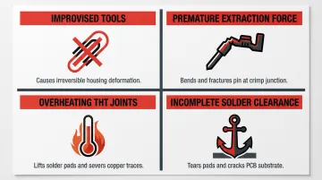
Common Mistakes That Cause PCB Pin Damage During Removal
Most PCB pin damage during removal is preventable. The four mistakes below account for the majority of bent pins, lifted pads, and cracked housings seen in the field.
Using Improvised Tools or Undersized Extractors
Paper clips, sewing needles, and toothpicks cannot depress a locking lance cleanly. They slip, score the plastic housing, and permanently deform the cavity. Use the extraction tool specified for the connector series and pin gauge.
Applying Extraction Force Before the Lance is Fully Released
Pulling the wire while the locking tab is still partially engaged bends the metal pin at the crimp point. It also destroys the housing lance and can strip the wire from the pin entirely. The pin should offer almost no resistance once correctly released.
Overheating THT Joints During Desoldering
Dwelling too long with the iron on a pad—especially on older, heat-weakened boards—lifts pads and severs the trace connection. IPC-7711/7721 recommends keeping the joint above liquidus temperature for no more than 30–60 seconds total, with peak dwell not exceeding 15–20 seconds.
Use flux to shorten heat dwell time. Never reheat the same joint repeatedly.
Failing to Clear All Solder Joints on a Multi-Pin Connector
Even one partially soldered pin acts as an anchor. Forcing extraction at that point tears the pad and risks cracking the board substrate — verify every joint is fully cleared before applying any upward pressure.
When to Reuse vs. Replace PCB Pins After Extraction
The decision to reuse or replace a pin directly affects long-term contact reliability. A pin that looks intact but has a slightly deformed barrel or work-hardened spring latch will have higher contact resistance and a shorter service life than a new pin.
Reuse is Acceptable When:
- The pin body is straight
- The crimp barrel is undamaged and still tightly secured to the wire
- The contact surface shows no corrosion or scoring
- The locking lance (if on the terminal) still springs back to its original profile
- A simple tug test on the wire produces the expected pull-force without the pin slipping
Replace the Pin When:
- The tip is blunted or bent beyond straightening
- The crimp barrel is cracked or the wire pulls free with minimal force
- Corrosion or pitting is visible on the contact surface
- The pin was removed from a high-cycle or high-reliability application such as medical or automotive electronics
In automotive applications governed by standards like USCAR-2 and LV214, reusing extracted components is effectively prohibited—no one has validated the extraction process under the stringent test conditions these standards require, and reuse would invalidate certification.
Connector manufacturers like Molex explicitly warn that the extraction process causes permanent deformation to the housing lance, which "decreases extremely" its retention strength. Molex mandates: "DO NOT REUSE the housing that withdrew terminals."
When sourcing replacement pins at volume, consistency matters as much as fit. Electropin's automatic die rolling process produces custom contact pins to tight tolerances with a defect rate of just 1 in 600,000,000—eliminating the variability that generic replacements typically introduce.
Frequently Asked Questions
Can I remove PCB pins without a special extraction tool?
While a small flat screwdriver can be used as a last resort for some connector types, improvised tools frequently damage the plastic housing or deform the pin. Proper extraction tools matched to the connector series are strongly recommended for reliable, damage-free removal.
What is the difference between removing a soldered pin and a connector-housed pin?
Soldered pins require the solder joint to be melted and cleared first using a soldering iron and desoldering pump. Connector-housed pins are released mechanically by depressing a locking lance with an extraction tool. Attempting to pull either type without the correct first step causes board or housing damage.
How do I remove a broken or stuck pin from a PCB connector?
For a broken terminal pin stuck in a housing, fine-tipped needle-nose pliers can be inserted from the rear to grip and twist the pin free. Inspect the housing cavity afterward for damage—the housing may need replacement if the lance is permanently deformed.
How do I avoid lifting pads when removing a soldered connector?
Pad lifting is prevented by clearing all solder from every pin hole before applying any mechanical force, using flux to reduce heat dwell time, and never forcing the connector out while any joint is still solid.
How do I know if a PCB pin is damaged after removal?
Visible signs include a bent or blunted tip, a cracked or loose crimp barrel, corrosion or pitting on the contact surface, and a locking lance that no longer springs back to position. Any of these indicate the pin should be replaced rather than reused.
Can the same pin be removed and reinserted multiple times?
Terminal pins are designed for a limited number of mating cycles — repeated removal fatigues the locking lance and degrades the contact surface. If your application requires frequent reconfiguration, select pins rated for higher cycle counts or contact Electropin to specify components built for your exact use case.